Loading New Records from Autoincrement Table
In this tutorial, we will show a simple Data Flow use case. We will load new records from a database to Salesforce. The source database table does not have any columns that store record creation time, but it has an autoincrement primary key column.
Skyvia import packages allow loading only new records from cloud apps easily. You can also use source data filtering in import for databases if the source table has a column, storing record creation time. However, when we need to use an autoincrement column to detect new records, such scenario requires a more complex tool like Data Flow.
Source Table
This tutorial uses the following MySQL table as an example:
1
2
3
4
5
6
7
8
9
10
11
12
13
14
15
CREATE TABLE demobase.customers (
  CustomerID int(11) NOT NULL AUTO_INCREMENT,
  CompanyName varchar(40) NOT NULL,
  ContactName varchar(30),
  ContactTitle varchar(30),
  Address varchar(60),
  City varchar(15),
  Region varchar(15),
  PostalCode varchar(10),
  Country varchar(15),
  Phone varchar(24),
  Fax varchar(24),
  Email varchar(50),
  PRIMARY KEY (CustomerID)
);
Its primary key column, CustomerID is AUTO_INCREMENT. It means that for every new record, CustomerID is increased by one. This allows us to determine the new records by remembering the max CustomerID value processed before.
We are going to import data from the customers table to the Account object in Salesforce.
To find out how to create a data flow package and configure mapping settings of nested objects correctly, read our step-by-step instruction below.
Creating Connections to Data Sources
First, you need to create connections in Skyvia. In our tutorial we will use a MySQL connection in a Source component and a Salesforce connection in a Target component.
Read the MySQL and Salesforce topics to find out how to configure settings of the specific database and cloud app as well as view the Connections topic to know how to create a connection following several simple steps.
Creating Data Flow Package
We start by creating a data flow package using the following steps:
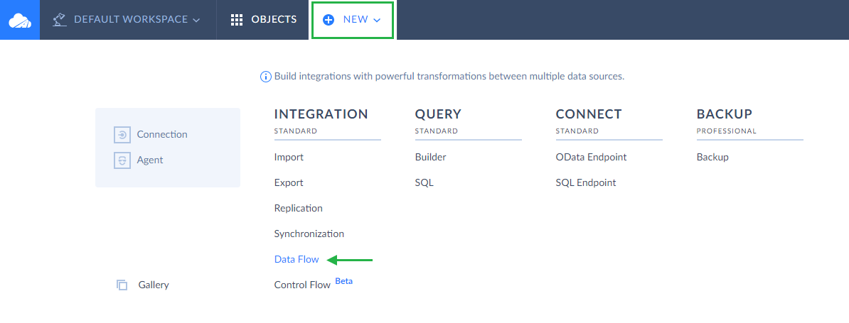
- Click +NEW in the top menu;
-
In the Integration column, click Data Flow;
- In the open package editor, rename your package by clicking and editing the package name. The default package name is Untitled. Please note that if you omit this step, the package name will remain Untitled in the list of created packages.
Creating Parameter
Data flow parameters can store values between data flow runs. In this tutorial we use a parameter to store the max primary key value in the table. Next time the data flow will run, it will query only records with a larger primary key value, and thus, only new records created since the previous run will be processed.
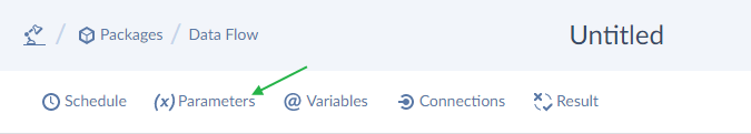
To create a parameter, click Parameters on the Data Flow editor toolbar.
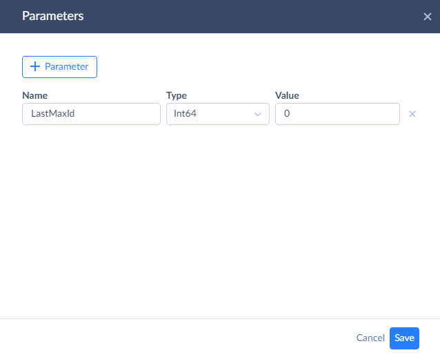
Then click + Parameter. Specify the parameter Name, Type, and Value. For the Name, we will use LastMaxId, but you can use any name. The new parameter must have a numeric type. Int64 is the most suitable. As for the Value, you can either specify 0 (which means that the first run will load all the records) or to the current max primary key value in your table (if you don’t want to load any old records).
After we created the parameter, let’s start adding components to the diagram.
Adding Source
Every data flow starts with the Source component. Drag the Source component from the component list to the diagram. After this the Source details sidebar opens on the right.
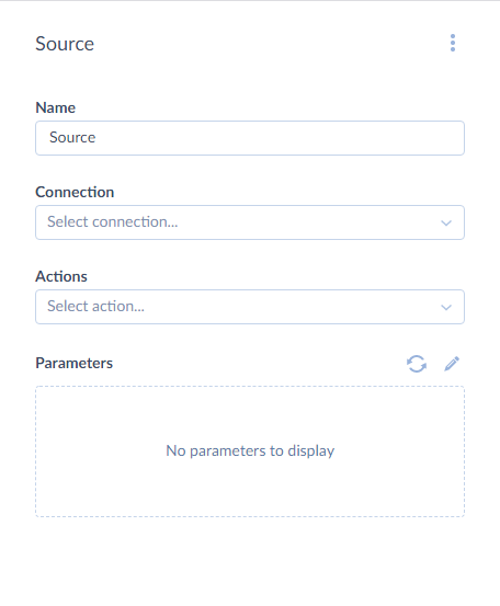
In this sidebar, first we need to select the MySQL connection. Then we select the Execute command action and specify the Command text for it. Here is the SELECT statement that selects new records from the customers table:
1
SELECT * FROM customers WHERE CustomerID > :MaxId
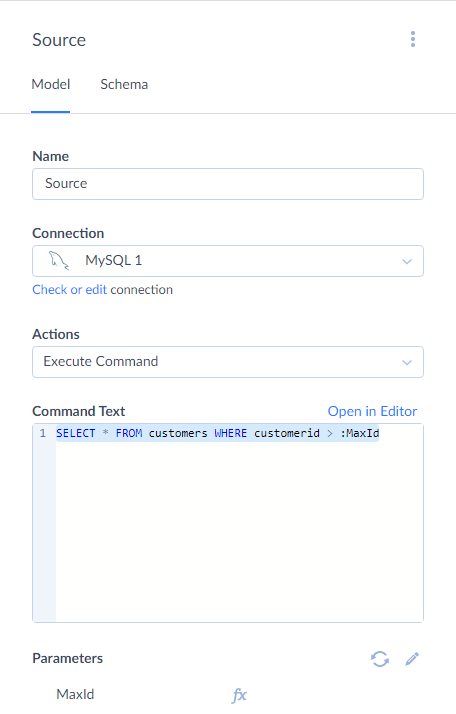
This statement uses the MaxId SQL parameter in the WHERE condition to filter out old records. Now we need to map this SQL parameter to our LastMaxId package parameter.
For this, click the MaxId parameter under the Command Tex box. This opens Mapping Editor.
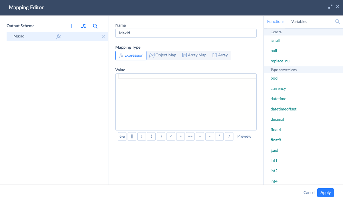
To quickly map it to the LastMaxId package parameter, click Variables in the top right corner of Mapping Editor and then click @LastMaxId. This adds the variable name to the Value box.
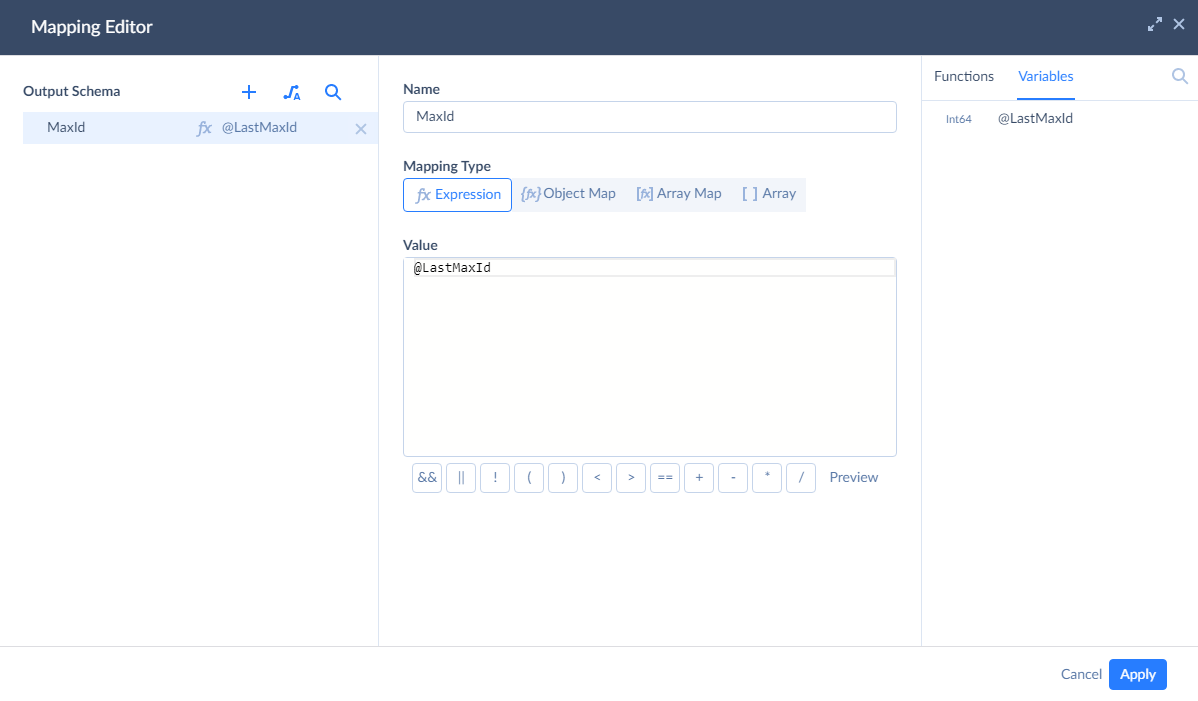
Finally, click Apply. Our Source component is configured.
Adding Value
Now we need to add a Value component to record the max CustomerId value from the processed records. Drag the Value component from the component list to the diagram. The Value details sidebar opens on the right.
Before configuring the Value component, we need to connect its input to the output of the Source component. Drag the circle on the bottom of the Source component to the Value component.
After this, let’s configure the Value component. In the Value box, enter CustomerID. In the Value type list, select Max. Finally, in the Variable box, select @LastMaxId and select the Update Variable on Data Flow Completion checkbox.
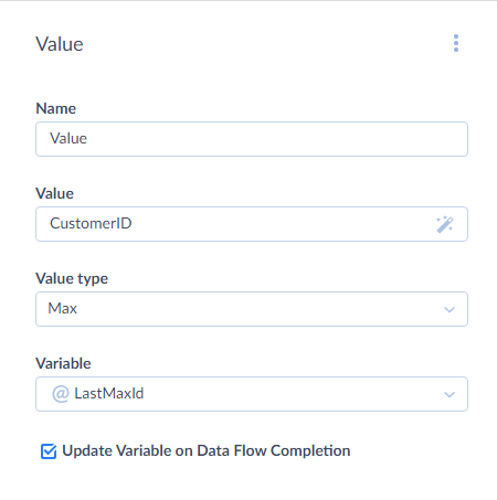
The Value component is configured, and we can proceed to adding a Target component.
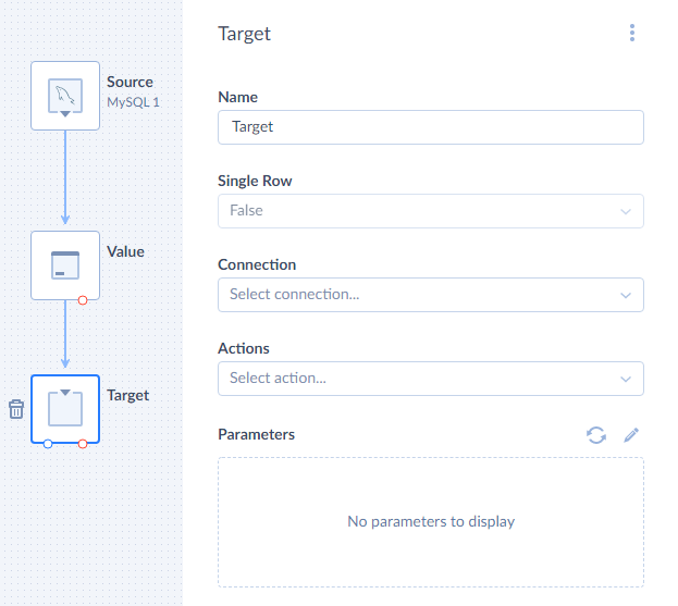
Adding Target
Drag the Target component from the component list to the diagram. The Target details sidebar opens on the right.
Connect the Value component output to the Target component as we did previously for the Value component. After this, we can configure the Target component.
First, we need to select our Salesforce connection. After this, in the Actions list, select Insert.
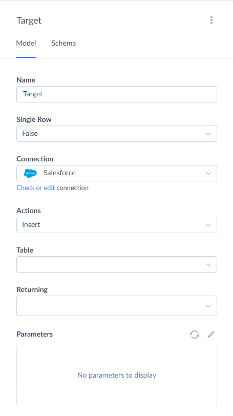
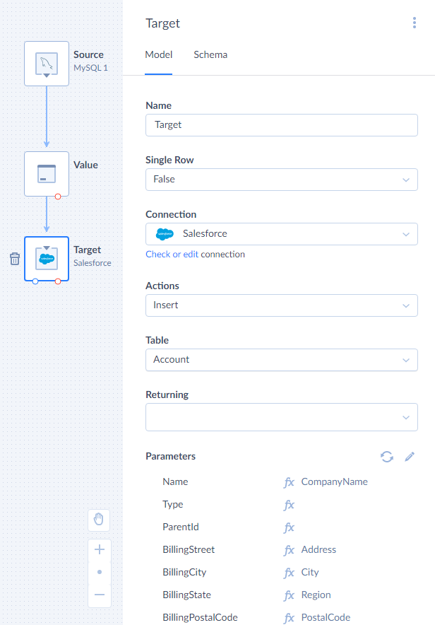
For the Insert action, we must select the Table to insert to and map action parameters, which correspond to the target table columns. Let’s select Account as Table and then select one of the parameters in the Parameters list to open the Mapping Editor.
In the Mapping Editor, first click the ![]() Auto Mapping button. It maps the action parameters to input properties with the same name automatically. In our case it maps the Phone and Fax parameters.
Auto Mapping button. It maps the action parameters to input properties with the same name automatically. In our case it maps the Phone and Fax parameters.
Then, we need to map other parameters manually, because their name are not the same as the names of the input properties. We must map the Name parameter, because this field cannot be null in Salesforce. Other parameters are not mandatory.
To map the Name parameter, select it in the list under Output schema, then click Properties in the top right corner of Mapping Editor and then click CompanyName. In a similar way, let’s map other parameters:
- BillingStreet to Address
- BillingCity to City
- BillingState to Region
- BillingPostalCode to PostalCode
- BillingCountry to Country
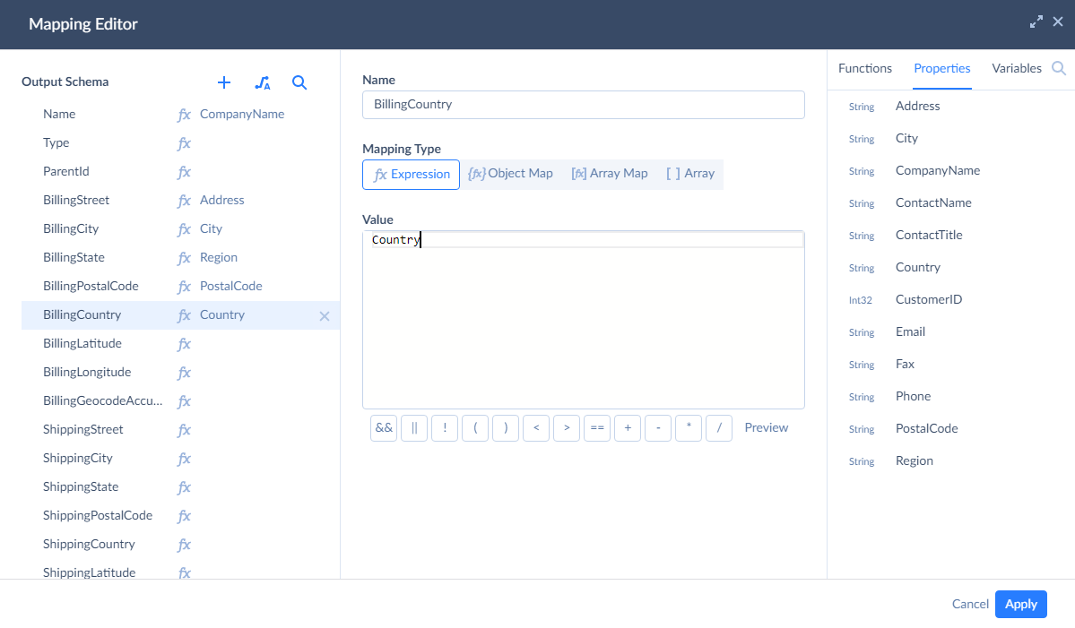
The mapping is configured, click Apply.
After this, we have a fully working data flow, which we can run immediately or schedule for automatic execution. However, if we run the data flow in this state, its run details will show 0 success rows and 0 failed rows, despite actually processing rows and doing its job. This is because Data Flow requires additional configuration steps to determine its results.
Configuring Results Settings
To record the numbers of success and failed records, we need to count the success and error records in the data flow itself. We will use Row Count components to count the rows, store the numbers to variables, and use these variables in Results Settings.
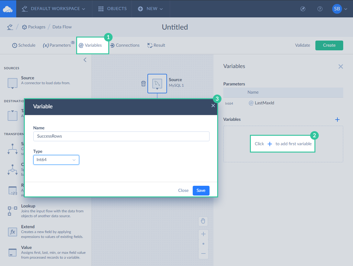
Variables
Let’s start with adding variables. Click Variables on the toolbar. In the Variables sidebar, click the plus button. Enter the variable name, for example, SuccessRows, and select Int64 in the Type list and then click Save.
Repeat these actions to add the FailedRows variable.
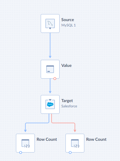
Row Count Components
Now drag two Row Count components to the diagram. Connect one of them to the regular output of the Target component (blue circle), and another one - to the error output (red circle).
Select the Row Count component, connected to the regular output, and in its details sidebar, select the SuccessRows variable.
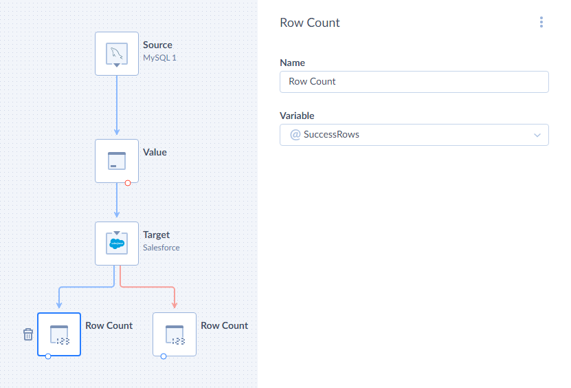
For another Row Count component, select FailedRows in its Variable list.
Result Settings
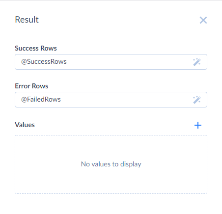
After we configured Row Count components, we need to set up the result settings. Click Result on the Data Flow editor toolbar to open the corresponding sidebar.
Here we need to specify, what number to take as the number of success records, and what - as a number of failed records. For the purpose of this simple tutorial, we can just type @SuccessRows in the Success Rows box, and @FailedRows in the Failed Rows box. However, in more complex cases with multiple target components, we may need to use more Row Count components, more variables, and enter expressions which calculate the necessary numbers out of multiple variables into these boxes.
Configuring Log
Now the data flow will display correct results. But what if some rows fail to load into Salesforce? We will know the number of failed rows, but we won’t know anything else. To fix these errors easier, it’s important to know which rows failed, and why they failed. To achieve it, we can write a log with error information in the data flow.
Creating Log
We need to create a log object first in order to write into it. To create a log object, click Connections on the Data Flow editor toolbar. The Connection sidebar opens.
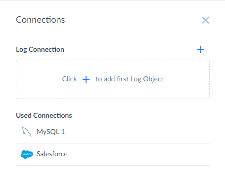
This sidebar lists all the connections used in the data flow and allows managing logs. To create a log object, click the plus button near Log connection.
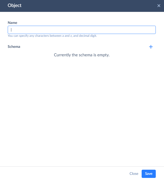
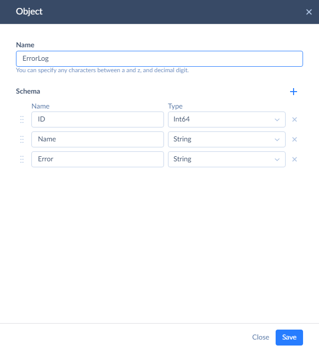
Enter a name for the log object, and then add columns to it by clicking the plus button and specifying their names and types. In this tutorial, let’s create three columns - to store the ID and name of failed records and the corresponding error message, returned by Salesforce.
Writing Log
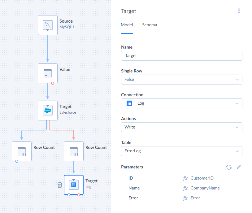
To write data to a log, you need to add another Target component. Add it to the diagram and connect it to the Row Count, which counts error rows of the first Target component. Then proceed to configuring the newly added Target.
In the Connection list, select Log. This target component will be used to write data to our log object, so select the created log object in the Table list.
After this, we need to map the action parameters, which correspond to the Log object columns. Select one of the parameters in the Parameters list to open the Mapping Editor.
In the mapping editor let’s map parameters to the following input properties:
- ID - to CustomerID
- Name - to CompanyName
- Error - to Error
Error is a new column, automatically added by the first Target component to its error output. It stores error messages, returned by Salesforce, for failed rows, and now we store them to our log.
Data Flow is Ready
That’s all. Now our data flow not only loads data but also displays correct results and writes the necessary information to the log in case of any errors. We can save it and then either run it manually immediately, or schedule for automatic execution. For more information about scheduling Data Integration packages, read Scheduling Packages for Automatic Execution